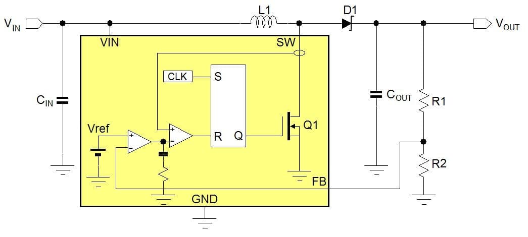
Circuit diagram of boost converter From Fig. 3, during the switch is
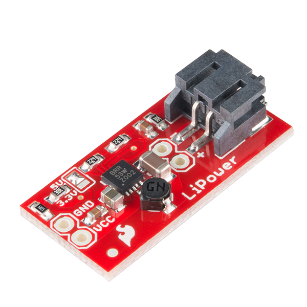
4.7 (479) · € 19.99 · Auf Lager

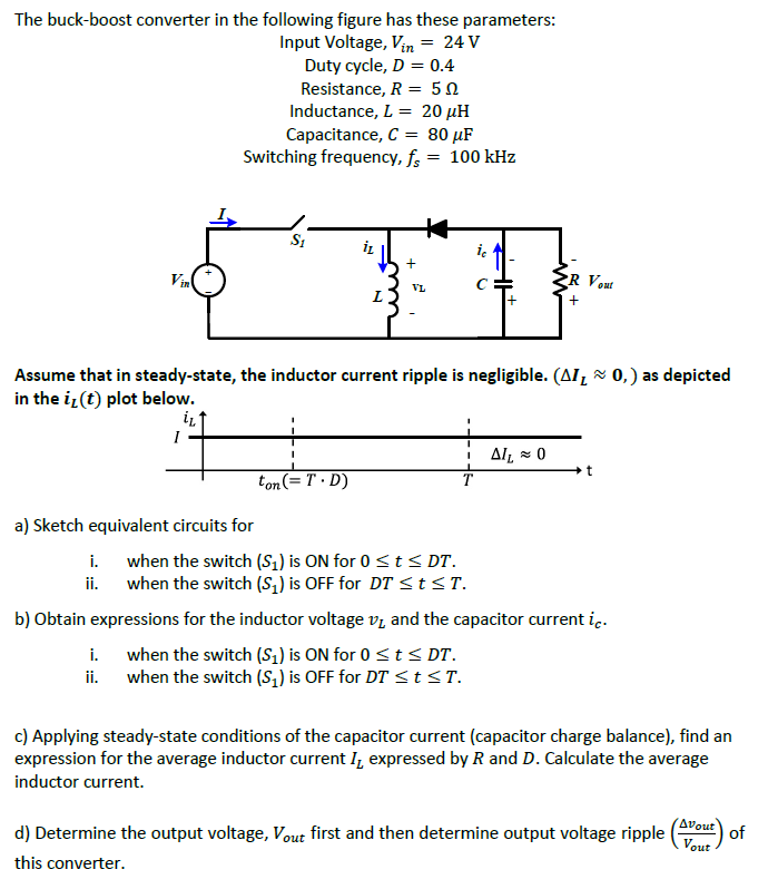
Solved The buck-boost converter in the following figure has
Electronics, Free Full-Text
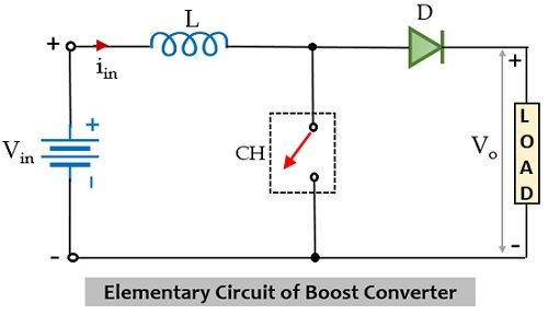
What is Boost Converter? Operating Principle and Waveform
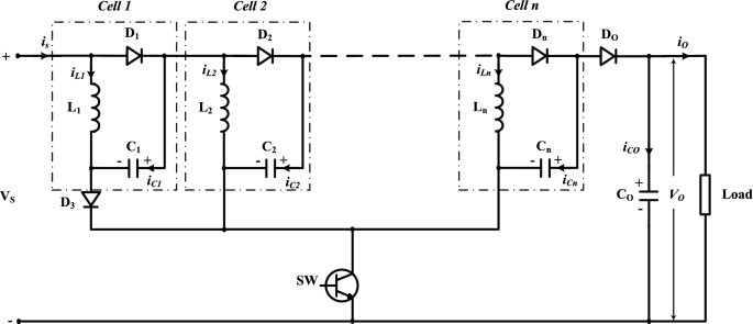
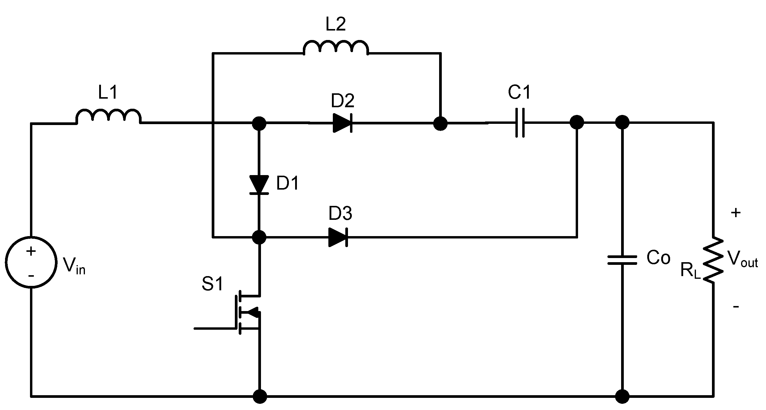
A new extended single-switch high gain DC–DC boost converter for

Understanding the Operation of a Boost Converter - Technical Articles
Energies, Free Full-Text

Boost Converter: Basics, Working, Design & Application

Design Note 183: The LT1370: A 500kHz, 6A Monolithic Boost
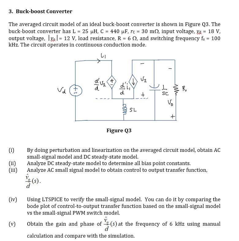
Solved 3. Buck-boost Converter The averaged circuit model of

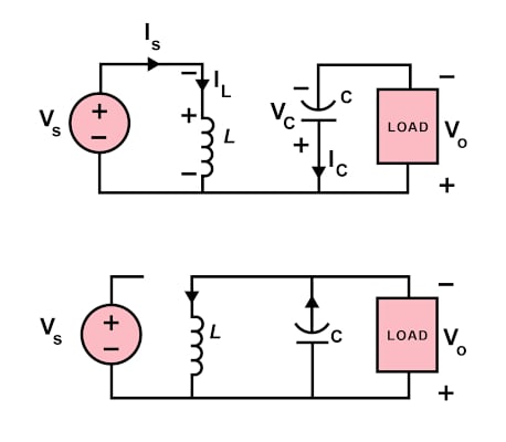
Schematic circuit of a buck converter (a), boost converter (b) and
inductor - The switch pin of boost converter seems to pull down

What is DC to DC Boost Converter? Working Principle, Waveforms
DC/DC Converters: Circuit Analysis–Intro to Predicting Circuit
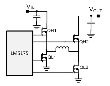
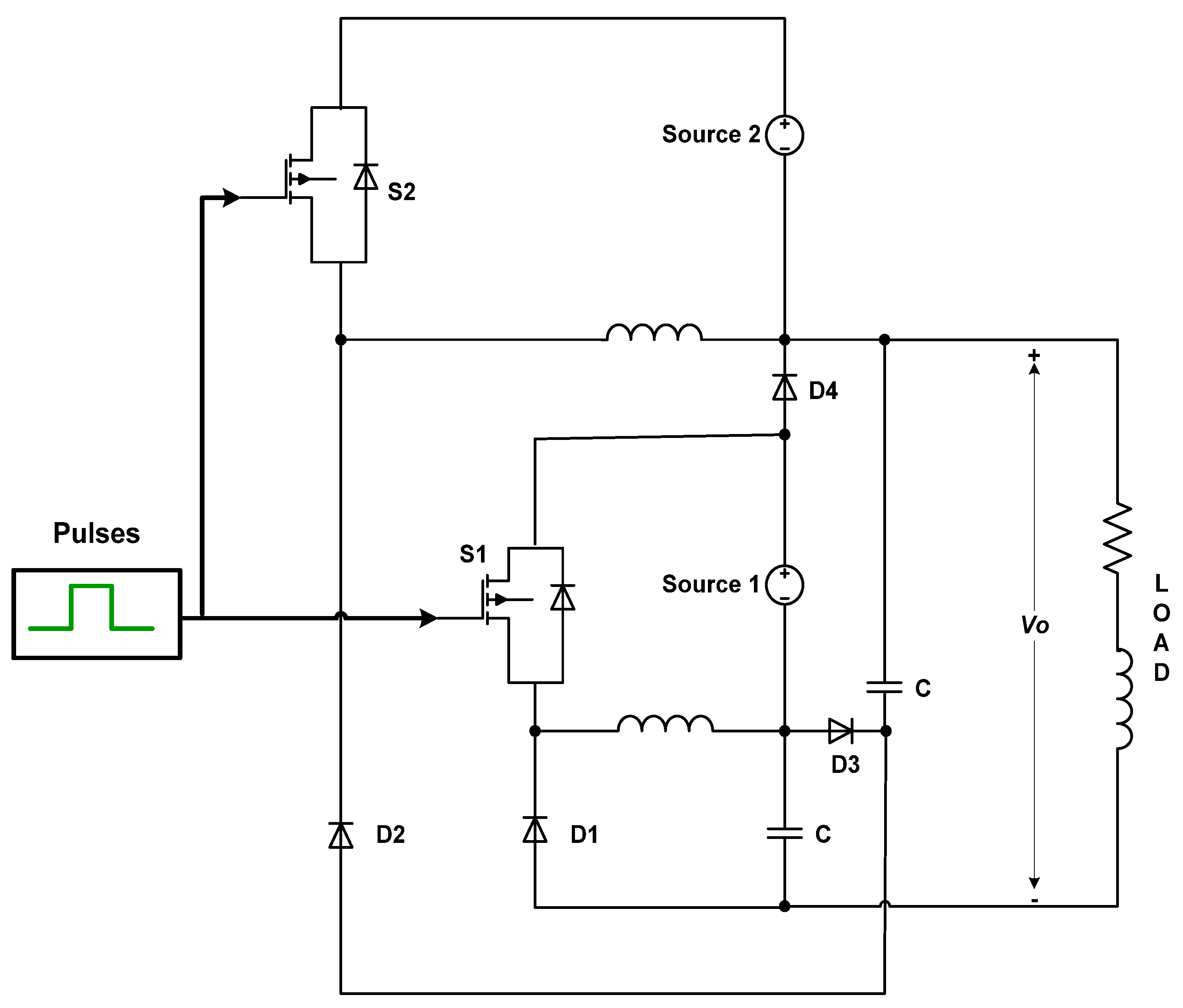
Four-switch buck-boost controller delivers high power and