Boost Converter - Circuit Diagram, Working & Waveforms
4.9 (184) · € 28.50 · Auf Lager
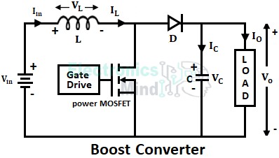
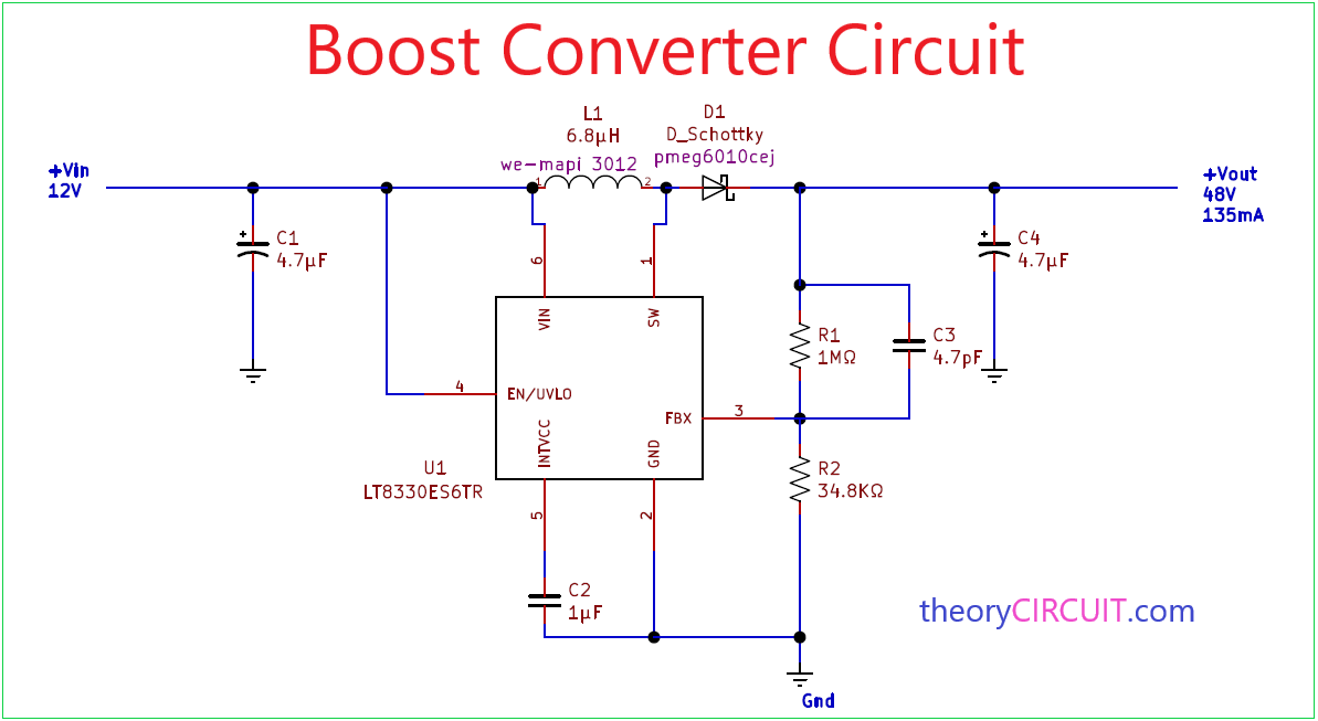
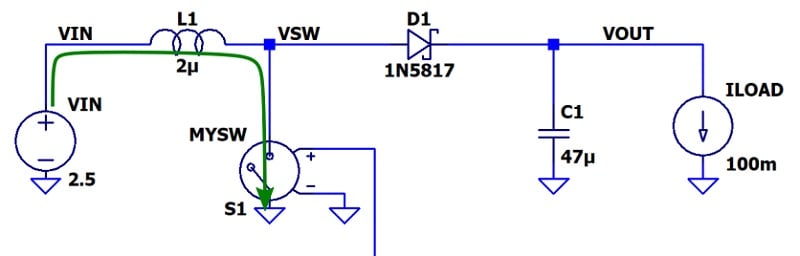
A boost converter is basically a step-up chopper or step-up dc-to-dc converter by which we can obtain an output voltage greater than the input voltage. In other words, boost converters are regulator

Waveforms at Continuous conduction mode of Boost converter

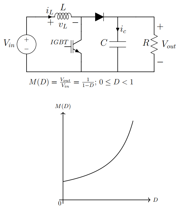
One-Quadrant Switched-Mode Power Converters - CERN Document Server
TPS63070: Buck/Boost converter TPS63070 is not working properly - Power management forum - Power management - TI E2E support forums
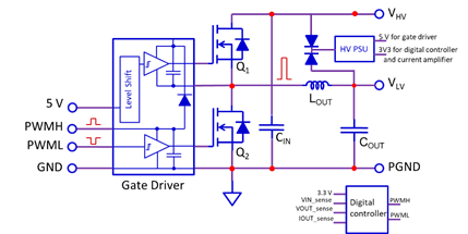
How to Design a 12V-to-60V Boost Converter with Low Temperature Rise Using eGaN FETs

Boost Converter: Design, Circuit, Equations & More

Buck–boost converter - Wikipedia
Boost Converters
What is the minimum value of the inductor in a buck-boost converter for it to continue operating in the continuous conduction mode (CCM)? - Quora
Understanding the Operation of a Boost Converter - Technical Articles
Boost Converter - Circuit Diagram, Working & Waveforms